SINGLE- AND MULTI CHANNEL SYSTEMS
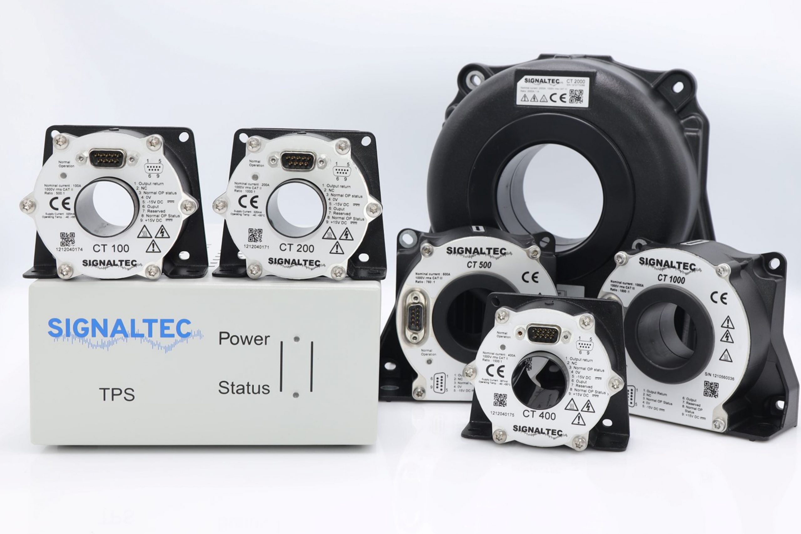
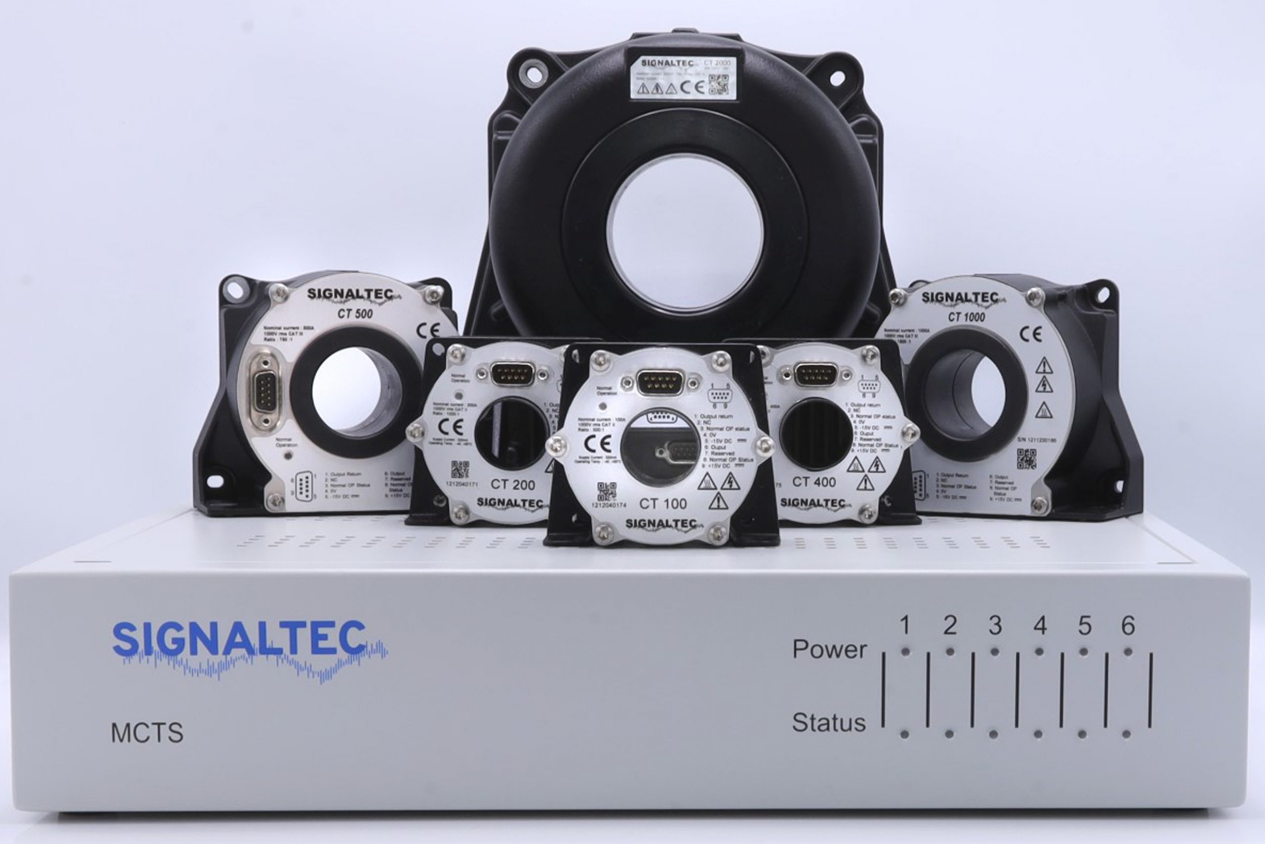
TPS II and MCTS II are complete systems consisting of power supply rack, current transducer, connection cable and burden module.

TPS II
Single Channel Transducer System

MCTS II
Multi Channel Transducer System
Videos
AC amplitude- and phase-test of the passive plug-on 1.5 ohms burden resistor between 1 kHz and 500 kHz. The active power is simulated with a two channel function generator and a connected wideband power amplifier.
The current- and phase angle-reference is channel 1 of a transient power meter. The burden resistor output is connected to the sensor input terminal of channel 2. The deviations between both current values and both phase angle values are calculated in the instrument (DEV. I and DEV. PHI). Current deviation around 0.5 % and 1 degree at 500 kHz.
The current- and phase angle-reference is channel 1 of a transient power meter. The plug-on amplifier output is connected to the sensor input terminal of channel 2. The deviations between both current values and both phase angle values are calculated in the instrument (DEV. I and DEV. PHI). Current deviation around 1.2 % and 0.7 degree at 100 kHz.
Upper instrument: Current output of one CT 500 sensor, scaling 750 : 1.
Lower instrument: Voltage output of active voltage amplifier, connected to the second CT 500, scaling 14 mV/A.
Do you know that you can double your power range if you use two current sensors in parallel. You can sum up both output current signals at one current input terminal of a power meter. See two parallel CT 500 measuring 1000 Arms (I1) in series to one CT 1000 (I2).
We normally recommend this for current levels above 5000 A since we do not have a real good AC transducer above the CTS 5000.
The current level varies between 20 A and 1000 A, the power factor between 0 and 1 (phase angle 90 … 0 degree).
Channel 1: I, P, PF and Phi measured with CT 1000 and a 2.5 meter connection cable.
Channel 2: I, P, PF and Phi measured with CT 1000 and a 30 meter connection cable.
Result at 50 Hz: Almost no influence of cable length visible.
